Product introduction
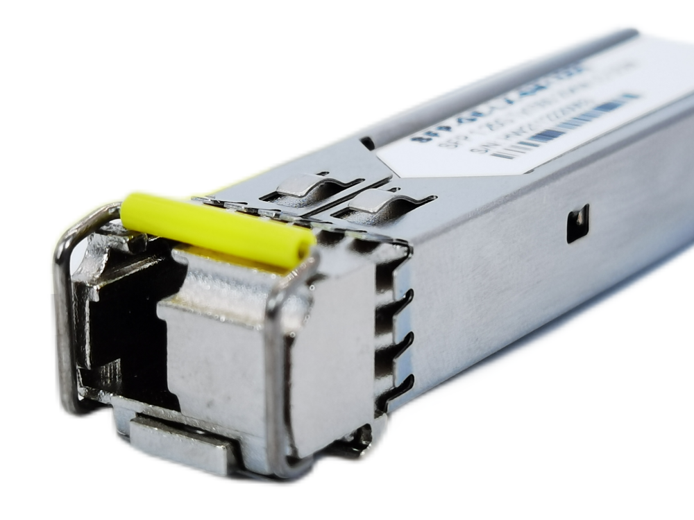
SFP transceiver optical modules, as an important part of optical fiber communication, are optoelectronic devices that realize the functions of photoelectric conversion and electro-optical conversion in the process of optical signal transmission.
The optical module works at the physical layer of the OSI model and is one of the core devices in the optical fiber communication system. It is mainly composed of optoelectronic devices (optical transmitters, optical receivers), functional circuits, and optical interfaces. The working principle of the optical module is shown in the working principle of the optical module.
The transmitting interface inputs electrical signals with a certain code rate, and after processing by the internal driver chip, the driving semiconductor laser (LD) or light-emitting diode (LED) emits a modulated optical signal of the corresponding rate. After transmission through the optical fiber, the receiving interface then transmits the optical signal. It is converted into an electrical signal by the light detection diode, and after passing through the preamplifier, the electrical signal of the corresponding code rate is output.
Module packaging

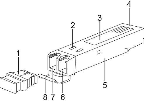
| SFP Transceiver Structure | Functional Use Description |
| 1. Dust Cover | Protect optical fiber connectors, optical fiber adapters, optical interfaces of optical modules, and ports of other devices from external environmental pollution and external force damage. |
| 2. Skirt Spring | It is used to ensure a good overlap between the optical module and the optical interface of the device and only exists on the optical module in the SFP package. |
| 3. Label | It is used to identify the key parameters and manufacturer information of the optical module. |
| 4. Connector | It is used for the connection between the optical module and the single board, to transmit signals, supply power to the optical module, etc. |
| 5. Metal Shell | To protect internal components, there are mainly two types of 1*9 shells and SFP shells. |
| 6. Receive Interface (Rx) | Optical fiber receiving interface. |
| 7. Transmit Interface (Tx) | Optical fiber sending interface. |
| 8. Handle Buckle | It is used to plug and unplug the optical module, and for the convenience of identification, the color of the handle buttons corresponding to different bands is also different. |
How to measure the performance indicators of optical modules
Optical module transmitter
1. Average transmitted optical power
The average emitted optical power refers to the optical power output by the light source at the transmitting end of the optical module under normal working conditions, which can be understood as the intensity of light. The transmitted optical power is related to the proportion of “1” in the transmitted data signal. The more “1”, the greater the optical power. When the transmitter sends a pseudo-random sequence signal, “1” and “0” account for roughly half each, and the power measured at this time is the average transmitted optical power, in W or mW or dBm. where W or mW is a linear unit and dBm is a logarithmic unit. In communication, we usually use dBm to express optical power.
2. Extinction Ratio
Extinction ratio refers to the minimum value of the ratio of the average optical power when the laser transmits all “1” codes to the average optical power when all “0” codes are transmitted under full modulation conditions, and the unit is dB. As shown in Figures 1-3, when we convert an electrical signal into an optical signal, the laser in the transmitting part of the optical module converts it into an optical signal according to the code rate of the input electrical signal. The average optical power when all “1” codes represent the average power of the laser emitting light, the average optical power when all the “0” codes represent the average power when the laser does not emit light, and the extinction ratio represents the distinguishing ability of 0 and 1 signals, so Extinction ratio can be seen as a measure of the operating efficiency of a laser. Typical minimum values for extinction ratios range from 8.2dB to 10dB.
3. The central wavelength of the optical signal
In the emission spectrum, connect the wavelength corresponding to the midpoint of the 50℅ maximum amplitude line segment. Different types of lasers or two lasers of the same type will have different center wavelengths due to process, production, and other reasons. Even the same laser may have different center wavelengths under different conditions. Generally, manufacturers of optical devices and optical modules provide users with a parameter, that is, the central wavelength (such as 850nm), which is generally a range. At present, there are three main central wavelengths of optical modules: 850nm band, 1310nm band, and 1550nm band.
Why are they defined in these three bands? This is related to the optical fiber loss in the transmission medium of the optical signal. Through continuous research and experiments, it is found that the fiber loss usually decreases with the increase of wavelength, the loss of 850nm is less, and the loss of 900 ~ 1300nm becomes higher; while the loss of 1310nm becomes lower, the loss of 1550nm is the lowest, and the loss above 1650nm tends to increase. So 850nm is the so-called short-wavelength window, and 1310nm and 1550nm are the long-wavelength windows.
Optical module receiver
1. Overload optical power
Also known as saturated optical power, it refers to the maximum input average optical power that the receiver component can receive under the condition of a certain bit error rate (BER=10-12) of the optical module. The unit is dBm.
It should be noted that the photodetector will have a photocurrent saturation phenomenon under strong light irradiation. When this phenomenon occurs, the detector needs a certain time to recover. At this time, the receiving sensitivity decreases, and the received signal may be misjudged. cause bit errors. To put it simply, if the input optical power exceeds this overload optical power, it may cause damage to the equipment. During use and operation, try to avoid strong light exposure to prevent exceeding the overload optical power.
2. Receive sensitivity
The receiving sensitivity refers to the minimum average input optical power that the receiving end component can receive under the condition of a certain bit error rate (BER=10-12) of the optical module. If the transmitted optical power refers to the light intensity of the transmitting end, then the receiving sensitivity refers to the light intensity that the optical module can detect. The unit is dBm.
In general, the higher the rate, the worse the receiving sensitivity, that is, the greater the minimum received optical power, and the higher the requirements for the device at the receiving end of the optical module.
3. Received optical power
The received optical power refers to the average optical power range that the receiving end components can receive under the condition of a certain bit error rate (BER=10-12) of the optical module. The unit is dBm. The upper limit of the received optical power is the overload optical power, and the lower limit is the maximum value of the receiving sensitivity.
In general, when the received optical power is less than the receiving sensitivity, the signal may not be received normally because the optical power is too weak. When the received optical power is greater than the overloaded optical power, the signal may not be received normally because of bit errors.
Comprehensive performance indicators
1. Interface rate
The maximum electrical signal rate that the optical device can carry without error transmission, the Ethernet standard stipulates -:125Mbit/s, 1.25Gbit/s, 10.3125Gbit/s, 41.25Gbit/s.
2. Transmission distance
The distance that an optical module can transmit is limited mainly by loss and dispersion. Loss is the loss of light energy due to absorption, scattering, and leakage of the medium when light is transmitted in the optical fiber. This part of the energy is dissipated at a certain rate with the increase of the transmission distance. Dispersion is mainly caused by the fact that electromagnetic waves of different wavelengths travel in the same medium at different speeds, resulting in different wavelength components of the optical signal arriving at the receiving end at different times due to the accumulation of transmission distances, resulting in pulse broadening and inability to distinguish the signal.
In terms of the limited dispersion of the optical module, the limited distance is much larger than the limited distance of the loss, which can be ignored. The loss limit can be estimated according to the formula: loss limited distance = (transmitting optical power – receiving sensitivity) / fiber attenuation. The attenuation of the optical fiber is strongly related to the actual selected optical fiber.
Classification of optical modules
1. Sort by the transfer rate
In order to meet the requirements of various transmission rates, optical modules with different rates are produced: 400GE optical modules, 100GE optical modules, 40GE optical modules, 25GE optical modules, 10GE optical modules, GE optical modules, and FE optical modules.
2. Sort by package type
The higher the transmission rate, the more complex the structure, resulting in different packaging methods. Most switches are suitable for package types: QSFP-DD, QSFP28, QSFP+, SFP28, SFP/e SFP, SFP+, CXP, CFP, etc.
3. Classification by optical transmission mode
Optical fibers are divided into single-mode optical fibers and multi-mode optical fibers. In order to use different types of optical fibers, single-mode optical modules and multi-mode optical modules are produced.
The center wavelengths of single-mode optical modules are generally 1310nm and 1550nm, which are used together with single-mode optical fibers. Single-mode fiber has a wide transmission frequency and large transmission capacity, which is suitable for long-distance transmission.
The center wavelength of the multimode optical module is generally 850nm, which is used together with the multimode optical fiber. Multimode fiber has modal dispersion defect, and its transmission performance is worse than that of single-mode fiber, but the cost is low, and it is suitable for small capacity and short-distance transmission.
Note: When using a long-distance optical module, the transmit optical power is generally greater than the overload optical power, so you need to pay attention to the fiber length to ensure that the actual received optical power is less than the overload optical power. If the length of the optical fiber is short, the optical attenuation of the optical fiber (the attenuation value per unit length of the optical fiber, in dB/km) needs to be used when using a long-distance optical module to avoid burning out the optical module at the opposite end.
3. Classified by central wavelength
The operating wavelength of the optical module is a range. For the convenience of description, the central wavelength is used, and the unit is a nanometer (nm). In order to support the use of different optical bands for optical signal transmission, optical modules with different central wavelengths are produced, such as 850nm, 1310nm, 1550nm optical modules, etc.
The biggest difference between color optical modules and other types of optical modules is that the central wavelength is different:
Generally, the central wavelengths of optical modules are 850nm, 1310nm, and 1550nm. The central wavelength is relatively single. We call this type of light “black and white light” or “gray light”.
The color light module carries several different central wavelengths of light, so the intersection is colorful, and we call this type of light “color light”.
Color optical modules are divided into two types: Coarse Collected Wave Optical Modules (CWDM) and Dense Wave Optical Modules (DWDM). In the same band, there are more types of dense wave optical modules, so the dense wave optical modules make more full use of the resources of the band. Lights with different center wavelengths can be transmitted in the same fiber without interfering with each other. Therefore, the light from the different center wavelengths of the multi-channel color optical modules is combined through a passive combiner for transmission. Different central wavelengths divide the light into multiple paths, effectively saving fiber lines. Color optical modules are mainly used in long-distance transmission lines.
Precautions for installation and use of SFP transceiver optical modules
Optical modules must have standardized operation methods in the application, and any irregular actions may cause hidden damage or permanent failure.
The main reasons for the failure of optical modules are the deterioration of optical module performance caused by ESD damage, and the failure of optical links caused by pollution and damage to optical ports. The main reasons for optical port pollution and damage are:
- The optical port of the optical module is exposed to the environment, and the optical port is polluted by dust entering.
- The end face of the optical fiber connector used has been polluted, and the optical port of the optical module is secondarily polluted.
- Improper use of the end face of the optical connector with pigtails, such as scratches on the end face, etc.
- Use inferior fiber optic connectors.
How to effectively protect the optical module from failure?
In order to ensure that the optical module can work well, it is mainly divided into ESD protection and physical protection.
ESD protection:
ESD damage is a major problem that causes the deterioration of optical device performance and even the loss of optoelectronic function of the device. In addition, optical devices damaged by ESD are not easy to be tested and screen, and it is difficult to quickly locate the failure if it fails.
Instructions:
- During the transportation and transfer of the optical module before use, it must be in an anti-static package, and must not be taken out or placed at will.
- Before touching the optical module, you must wear anti-static gloves and anti-static wristbands, and you must also take anti-static measures when installing optical components (including optical modules).
- The test equipment or application equipment must have a good ground wire.

Physical protection:
The internal laser and temperature control circuit (TEC) of the optical module are relatively fragile, and they are easy to break or fall off after being hit. Therefore, physical protection should be paid attention to during transportation and use. The dirt on the optical port can be wiped lightly with a cleaning cotton swab. Non-specialized cleaning rods may damage the optical port. Excessive force on the cleaning cotton swab may cause the metal in the cotton swab to scratch the ceramic end face. The insertion and extraction of the optical module is simulated by manual operation, and the design of push and pull forces is also simulated by manual operation. Appliances must not be used during the installation and removal process.
Instructions:
- When applying the optical module, be careful to handle it with care to prevent it from falling.
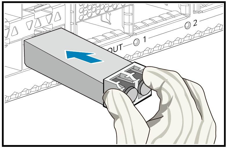
- When the optical module is inserted, push it in by hand and cannot use other metal tools; when pulling out, first open the pull ring to the unlocked position and then pull the pull ring, and cannot use other metal tools.
- When cleaning the optical port, a special cleaning cotton swab should be used, and other metal substances cannot be inserted into the optical port.

For reprints and citations, please indicate the source of the author of the article
